Wing incidence / setup
This short tutorial about wing incidence and the flight attitude, is an English translation of my work in the French Forum Retroplane. For the original article, in French, check here
So, here is my method to calculate the wing incidence during the building process. This is not the ultimate way to find and compute the wing incidence of an aircraft, but that the one I use with success for a while now.
The method described here apply only during the building stage, but if your plane / glider is already built (from plan, kit or RTF) the method apply, but this time, you need to use an Incidence-meter.
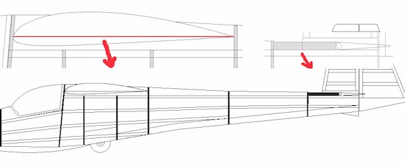
When I design a plan, I use Tracfoil to compute profiles. One of the advantage of Tracfoil, is that he give you the median line of the profile. This is the line I use for reference during the incidence process. Talking about reference, you must have a fixed reference point. here, I'll show 2 type. The first reference will be the fixed elevator, and the second one, the fuselage.
Wing Incidence calculation :
The elevator profile shown on the picture is flat, but the method, like the wing, apply if the elevator use a profile (median line)
The profile used here is a ClarkY. The median line of the profile is in red.
To have the incidence, you just need to extend the 2 references :
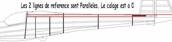
Here, the 2 lines are parallel, meaning that the incidence is 0 degrees.
The best wing incidence for 99% of the profiles are situated between 0 and 2 degrees, 1 to 1.5 will be the most used reference.
Incidence to 0, the fuselage will look straight in flight.
Using a geometric method, I want a positive incidence of 1.49 degrees. For a positive angle of attack, you lower the trailing edge, and move up the leading edge. Turbocad is used here, but in a paper printed plan, you can use 2 big rulers or balsa strips.
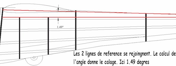
Now, the angle between the median line of the profile, and my fixed reference (the elevator) is 1.49 degrees. that will be my wing incidence.
Easy, simple geometric method. If the model is already built, with an Incidence-Meter, find the 0 angle, then move the with to the good angle using different height of wood under the wing profile (at the LE).
The flight attitude :
Most of the vintage glider, when fly level, looks like the nose is pointing to the ground. To reproduce that in a scale glider, we simply have to change the incidence of the wing / elevator to the fuselage.
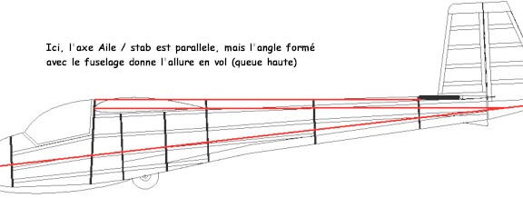
This time, the incidence between the wing and the elevator is 0, but the angle with the fuselage is here at around 6 degrees. The nose is going down, achieving the scale look in the air (tail high). Note that here, you can always change the wing incidence with the elevator.
But no worries here, you don't need to be precise to the 1/4 of mm or degrees ! The main thing is to stay between 0 and 2 degrees of incidence and everything will be fine.
For those who really want to spend more than 5 minutes finding the good incidence, here is a website (in French.. But the formulas are enough...)
http://www.chez.com/aerodynamique/angles.html
You can see here that the incidence will depend of the profile used on the glider, but we find than for the example of the E193, that the good incidence wing / fuselage is -5.7 (in the example here, incidence made visually and calculated afterwards gave us -6 degrees...Not bad in 2 minutes and without any maths ! :o) )
And don't forget to change your centre of gravity as you change the incidence as both depend on each other... But that will be another story ! :o)